SINGLE-SCREW COMPRESSORS
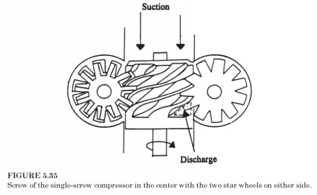
In the single-rotor compressor designed by French physicist and engineer, Bernard Zimmern, which began its work of the compressor in the early 1960s. French and us patents were issued in 19641965. Initial sales in the US were out of the car, compressing the air, but cooling model followed. Screw single-rotor compressor represents a cylindrical member with spiral grooves, shown in the center of Fig. 5.35. Mating screw in the two plane asterisks on both sides of the screw, rotating in opposite directions from each other.
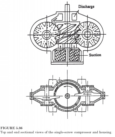
These stars wheels rotating in the plane of the center of the screw shaft. Gas-tight housing embodies the screw and stars Fig. 5.36, and the screw rotates with a small gap in the cylindrical fireplace that is a part of the body.
Mantel contains two slots in which the wheels star run. Only the screw is controlled from the outside, and the screw, then drives two stars. Capacity management is using a variable return port is controlled sliding vane, which regulates the position in which the compression begins.
Compression occurs simultaneously in the upper and lower halves of the compressor.
The results of this joint action in negligible net radial loads on the bearings of the screw. The only loads on the bearings in a machine other than the weight of parts, small loads on the wheel of stars of shafts high-pressure gas operating on one side of each tooth in the process of creating the grid.
Machine and two-screw compressor has few moving partsone screw and two star wheels. Manufacurers seek to extend favorable compression efficiency to a lesser extent than now, suitable for two-screw compressor. In the development of single-screw compressors one of the difficulties was the disclosure of the materials for the wheel of stars that prevent wear. Currently, manufacturers of single-screw compressors seem to prefer a composite of steel and glass-fiber reinforced plastic.
When viewing the screw compressor package, for example, as shown in Fig. 5.33, oil separator is the large size of the component. Were some of the concepts developed in order to exclude this component package size may be reduced. One of such methods is to seal the gaps between the star wheels and a rotor with the help of liquid refrigerantsame refrigerant compressor pumps. Oil is still need for lubrication, but none is entered for sealing. Compressors are designed for sealing liquid refrigerant is constructed with small gaps between the star rotor wheels and what is the truth, compressors, sealed with oil. This concept can be applied for Halocarbon refrigerants such as R-134a and R-22, and air-conditioning, where the pressure ratio is moderate. The use of liquid refrigerant seals so far not been successful in ammonia compressors, nor for industrial refrigeration applications.
 .. ..
|

 ..
..