Screw compressors
Screw compressor can be visualized in the form of a gear pump. For gas compressor rotor profiles are designed to give maximum working volume, not the number of clearance where rotors mesh together. The pitch of the helix is that the input and output ports can be arranged at the ends, not on the side. The solid parts screws slide gas ports to separate one from the stroke, so that no inlet or outlet valves are needed.
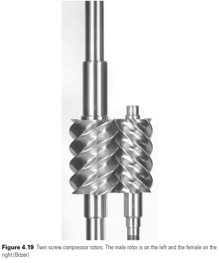
The more common form of two grid rotors on the parallel shafts (see Fig. 4.19 and 4.23). These, in turn, within carefully adjusted case, the space between the two grooves comes in front of the port, and gas flows. Still turn in the pocket of gas is sealed from the input port and headed down the barrels. Association share of the rotor, pocket decreases the compression volume of gas that is finally released at the opposite end of where power outlets are uncovered movement of the pistons. Various combinations of rotor size and number of petals were successfully applied. In most models of women's rotor is driven by the rotor, and research on optimization of the design of the rotor for refrigeration applications informs Stosic et al.
(2003). Maintenance of adequate lubrication is essential. Lubrication, cooling and sealing between the working part, as a rule, to the pumping of oil along the length of the trunk. This oil should be separated from the gas injection, and then cooled and filtered before returning to lubricate the chain.
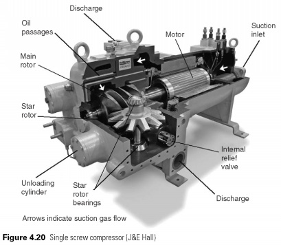
Single screw compressor has one of corrugated rotor rotating star tooth seal blades limit the pockets of gas, as they move along the rotor flute (see Fig. 4.20). Again, various geometries are possible, but compressors, currently manufactured rotor with six flute and eleven stars with teeth. In a normal situation is two stars, one on each side of the rotor. Each rotor of the flute, thus, used twice in each revolution of the main rotor and the gas pressure-balanced rotor, and the result will be much easier, bearing loads, than for the corresponding twin screw design. Stars are formed on the basis of the rotor, and because the torque is transmitted to the lubricant grid easier. Oil cooling and sealing usually, and oil circuit, similar twin screw.
Screw compressors clearance volume and no loss VE due to re-growth, as in a piston engine. The volume of losses in the result, mainly, of refrigerant leakage ago suction through the built-in spaces. Oil is used for sealing, but leakage of oil, which contains dissolved refrigerant, reduces the VE as the release of refrigerant and heat gas. FIVE decreases with increasing pressure ratio, but to a lesser extent than some types of pistons (Fig. 4.16). Leakage functions of the Council speed, so that smaller machines must operate at a high speed to maintain efficiency. With synchronous motor drives, this sets a lower practical limit on the size (Fig. 4.2).
All screw compressors, gas volume will be reduced to a given proportion input volume output port is open, and it is the ratio of the volume. Currently the gas inside the screws are open to the condenser pressure, and gas will flow to or via the port of discharge if the pressure is not equal.
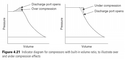
Power input screw compressor will be to maintain optimal only when the working pressure ratio corresponds to the volume. Over and under compression losses can be displayed as additional areas on the indicator diagram in Fig. 4.21. This results in IE you have, having a pronounced peak, as shown in Fig. 4.18 . To the left of the peak, over-compression of gas leads to a loss of efficiency, and on the right under compression with reverse flow of the gas-compression pocket when discharging port is open. Change the size of the output port of the changes in the position of the peak, and it illustrates the two curves in Fig. 4.18. Screw compressor should be selected so that the volume ratio suitable for the application. Leakage is also contributing to the loss of efficiency, but the friction effects are very small.
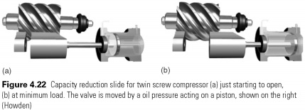
Capacity reduction screw compressor is carried out with the help of a sliding block cover part of the wall of the cylinder, which allows gas to return to the suction, therefore, varying stroke (Fig. 4.22). It is usual for the sliding part of the stem to adjust the size of the outlet port at the same time, so that the volume ratio of at least approximately maintained at part load. Many design variations and control methods exist. One screw-type, as a rule, have two mobile cranes, cranes are sometimes used instead of the slide. A reduction of up to 10% of the maximum capacity usual.
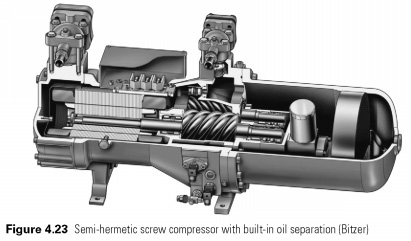
In oil separation, cooling and filtration screw compressor complicate an otherwise simple machines. Liquid injection is sometimes used instead of oil cooler. Some commercial screw compressors oil-processing circuit embedded in the Assembly. On Fig. 4.23 suction gas enters the suction pipe to the left, passes through the engine, with the help of the compressor, in the multi-stage separator to the right and then back to the port of discharge.
 .... ....
|


 ....
....