What are chillers
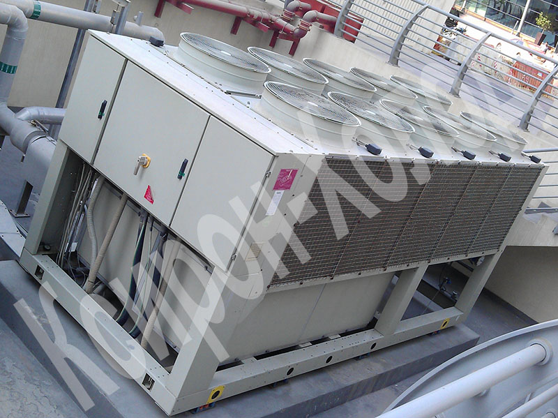
Chiller (chiller) is a refrigeration unit (refrigerator) for cooling water or other liquids. The chiller is designed to take heat from the medium to be cooled at low temperatures, while heat transfer at high temperatures is a side process. The chiller includes several functional elements: a compressor (from 1 to 4), a condenser, an electric motor, an evaporator, a device for expanding the refrigerant or a thermostatic valve, and a control unit.
Obtaining artificial cold is based on simple physical processes: evaporation, condensation, compression and expansion of working substances. The working substances used in refrigeration units are called refrigerants.
Chillers vary:
- by design (absorption, with built-in or remote capacitor - condenser and non-condenser);
- type of condenser cooling (air or water);
- wiring diagrams;
- having a heat pump.
Benefits
- Ease of use - year-round automatically maintains the set parameters in each room in accordance with sanitary standards;
- System flexibility - the distance between the chiller and fan coils is limited only by the capacity of the pump and can reach hundreds of meters;
- Economic advantage - reduced operating costs;
- Environmental advantage - harmless coolant;
- Building advantage - flexibility of layout, minimal usable space for placing a refrigeration machine, because it can be installed on the roof, on the technical floor of buildings, in the courtyard;
- Acoustic advantage - low noise design of units;
- Safety - the risk of flooding is limited by the use of shutoff valves.
Chillers can serve it only as a source of cold supply, but also in the mode of reversing the refrigeration or water cycle, operate as a heat pump, which is in demand in the cold season.
Types of chillers
Absorption chillers
The absorption type is a very promising area for the development of refrigeration technology, which is gaining wider application due to the pronounced modern tendency to save energy. The fact is that for absorption chillers, the main source of energy is not electric current, but waste heat, which inevitably arises in factories, enterprises, etc. and irrevocably released into the atmosphere, be it hot air, hot water cooled by air, etc.
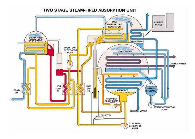
The working substance is a solution of two, sometimes three components. The most common binary solutions from the absorber (absorbent) and refrigerant meet two main requirements for them: high solubility of the refrigerant in the absorbent and a significantly higher boiling point of the absorbent compared to the refrigerant. Water-ammonia solutions (ammonia-water chillers) and lithium bromide (lithium bromide machines) are widely used, in which, respectively, water and lithium bromide are absorbents, and ammonia and water are refrigerants. The working cycle in absorption chillers (see the figure below) is as follows: in a generator to which waste heat is supplied, the working substance boils, as a result of which almost pure refrigerant boils, because its boiling point is much lower than that of the absorbent.
Refrigerant vapor enters the condenser, where it cools and condenses, losing its heat to the environment. Further, the resulting liquid is throttled, as a result of which it cools during expansion) and is sent to the evaporator, where, evaporating, it gives its cold to the consumer and goes to the absorber. Absorbent is supplied here through the throttle, from which coolant has boiled off at the very beginning and absorbs the vapors, because we have indicated the requirement for their good solubility above. Finally, the absorbent saturated with refrigerant is pumped to the generator, where it boils again.
Main benefits of absorption chillers:
- The ideal solution for creating trigeneration in the enterprise. The trigeneration complex is a complex that allows today to minimize the cost of electricity, hot water, heating and cooling for the enterprise by using its own cogeneration power plant in conjunction with an absorption chiller;
- Long service life - within 20 years, until the first major overhaul;
- low cost of produced cold, cold is produced almost for free, because absorption chillers simply utilize excess heat;
- Reduced noise and vibration, as a result of the lack of compressors with electric motors, as a result - quiet operation and high reliability;
- The use of refrigeration / heating units with a direct-acting flame gas generator allows abandoning boilers that must be used in conventional installations. This reduces the initial cost of the system and makes absorption chillers competitive compared to conventional systems that use boilers and coolers;
- Ensuring maximum energy savings during peak periods. In other words, without consuming electricity to produce cold / heat, absorption chillers do not overload the enterprise’s power supply even at peak times;
- It is possible to integrate into district steam systems with an effective double-effect refrigeration unit;
- It is possible to distribute the load under conditions of maximum performance in cooling mode. The device copes with the critical load in cooling mode with a minimum of energy consumption through the use of coolers with a direct-acting flame gas generator or a steam-heated generator;
- Allows the use of smaller emergency power generators, since the energy consumption of absorption refrigeration units is minimal when compared with electric refrigeration units;
- Safety for the ozone layer, does not contain ozone-depleting refrigerants. Cooling is carried out without the use of substances containing chlorine;
- The overall environmental impact is reduced to a minimum, as the consumption of electricity and gas, causing the greenhouse effect and as a result of global warming, is reduced.
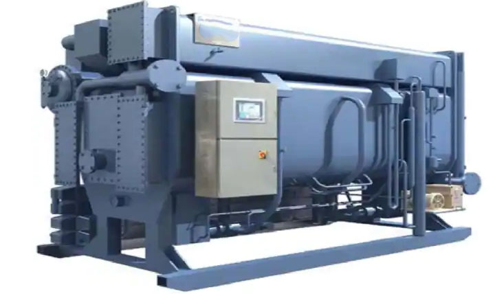
An absorption chiller is a machine that produces chilled water using residual heat from sources such as steam, hot water or hot gas. Chilled water is produced according to the principle of cooling: a liquid (refrigerant), which evaporates at a low temperature, absorbs heat from its environment during evaporation. Pure water is usually used as a refrigerant, while lithium bromide solution (LiBr) is used as an absorbent.
How absorption refrigeration systems work
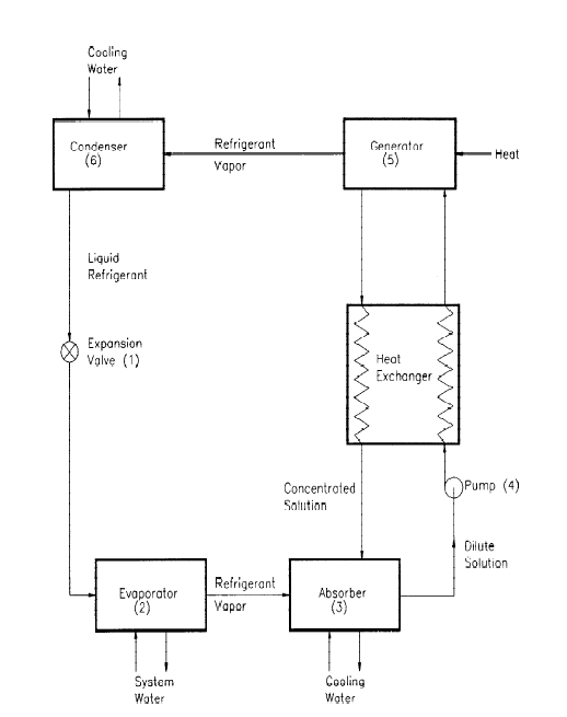
In absorption refrigeration units, the absorbent, generator, pump and heat exchanger replace the compressor of the steam compressor cooling system (mechanical cooling). The remaining three (3) components, also found in mechanical refrigeration systems, i.e. an expansion valve, evaporator and condenser, are also used in absorption refrigeration systems.
Evaporation stage of absorption coolers
Refer to Figure-2 for a schematic explanation of absorption cooling. Like mechanical cooling, the cycle “begins” when the high-pressure liquid refrigerant from the condenser passes through the expansion valve (1, in FIG. 2) into the low-pressure evaporator (2, in FIG. 2) and collects the Sump in the evaporator.
At this low pressure, a small amount of freon begins to evaporate. This evaporation process cools the remaining liquid refrigerant. Similarly, the transfer of heat from relatively warm process water to the currently cooled refrigerant causes the latter to evaporate (2, in FIG. 2), and the resulting steam is supplied to the low pressure absorber (3, In FIG. 2). As process water loses heat to the refrigerant, it can be cooled to significantly low temperatures. At this stage, chilled water is actually obtained by evaporating freon.
Absorption Stage of Absorption Coolers
The absorption of refrigerant vapor in lithium bromide is an exothermic process. In the absorber, the refrigerant is “absorbed” by the absorption solution of lithium bromide (LiBr). This process not only creates a low pressure region that draws a continuous stream of refrigerant vapor from the evaporator to the absorber, but also causes the vapor to condense (3, in FIG. 2), since it releases the heat of vaporization provided in the evaporator. This heat, together with the heat of dilution that occurs when the refrigerant condensate is mixed with absorbent, is transferred to cooling water and released in the cooling tower. Cooling water is a utility at this stage of cooling.
Regeneration of lithium bromide solution
As the lithium bromide absorbent absorbs the refrigerant, it becomes more and more diluted, reducing its ability to absorb more refrigerant. To continue the cycle, the absorbent must be re-concentrated. This is achieved by constantly pumping the diluted solution from the absorber to a low-temperature generator (5 in Figure 2), where the addition of residual heat (hot water, steam or natural gas) boils (4, in Figure 2) the refrigerant from the absorbent. Often this generator is used to recover waste heat from the factory. As soon as the refrigerant is removed, the re-concentrated lithium bromide solution is returned to the absorber, ready to resume the absorption process, and free freon is sent to the condenser (6, in Fig. 2). At this stage of regeneration, waste heat from steam or hot water is useful.
Condensation
The refrigerant vapor welded in the generator (5, in Figure 2) returns to the condenser (6), where it returns to its liquid state when cooling water raises the heat of vaporization. Then it returns to the expansion valve, where the full cycle ends. In the condensation step, cooling water again becomes useful.
Various technologies for absorption chillers
Absorption chillers can be disposable, double or newest, which is a triple effect. Machines with one effect have one generator (see the diagram above, Figure 2) and have a COP value of less than 1.0. Double-effect machines have two generators and two capacitors and are more efficient (typical COP values> 1.0). Triple effect machines add a third generator and capacitor and are the most efficient: a typical COP value of> 1.5.
Pros and cons of absorption chiller systems
The main advantage of absorption chillers is lower energy costs. Costs can be further reduced if natural gas is available at a low price or if we can use a low-grade heat source that would otherwise be lost in the factory.
The two main drawbacks of absorption systems are their size and weight, as well as their need for larger cooling towers. Absorbers are larger and heavier than electric chillers of the same capacity.
Steam Compression Chillers
Steam compression chillers are currently the most common type of refrigeration equipment. Cold generation is carried out in the vapor compression cycle, consisting of four main processes - compression, condensation, throttling and evaporation - using the four main elements - compressor, condenser, control valve and evaporator - in the following sequence: The working substance (refrigerant) is supplied to the gaseous state the compressor inlet with a pressure of P1 (~ 7 atm) and a temperature of T1 (~ 5C) and is compressed there to a pressure of P2 (~ 30 atm), heating up to a temperature of T2 (~ 80C).
Then freon goes to the condenser, where it is cooled (usually due to the environment) to a temperature of T3 (~ 45 ° C), while the pressure ideally remains unchanged, but actually drops by tenths of a bar. During cooling, the freon condenses and the resulting liquid enters the throttle (an element with high hydrodynamic resistance), where it expands very quickly. The output is a vapor-liquid mixture with parameters P4 (~ 7 atm) and T4 (~ 0С), which enters the evaporator. Here, freon gives its cold to the coolant flowing around the evaporator, heating up and evaporating at constant pressure (in reality, it will fall to tenths of an atmosphere). The resulting cooled coolant (Tx ~ 7C) is the final product. And it at the outlet of the evaporator has the parameters P1 and T1, with which it enters the compressor. The cycle closes. The driving force is the compressor.
Refrigerant and coolant
Of particular note is the separation of similar at first glance terms - refrigerant and coolant. Refrigerant is a working substance of the refrigeration cycle, during which it can be in a wide pressure range, and also undergoes phase changes. The coolant does not change the state of aggregation (phase changes) and serves to transfer (transfer) heat (cold) to a certain distance. Of course, we can draw an analogy by saying that the compressor is driven by a compressor with a compression ratio of about 3, and the coolant is a pump that increases pressure by 1.5-2.5 times, i.e. the figures are comparable, but the fact of the presence of phase changes in the refrigerant is fundamental. In other words, the coolant always works at temperatures below the boiling point for the current pressure, while the refrigerant can have a temperature both below and above the boiling point.
Classification of vapor compression chillers
By installation type:
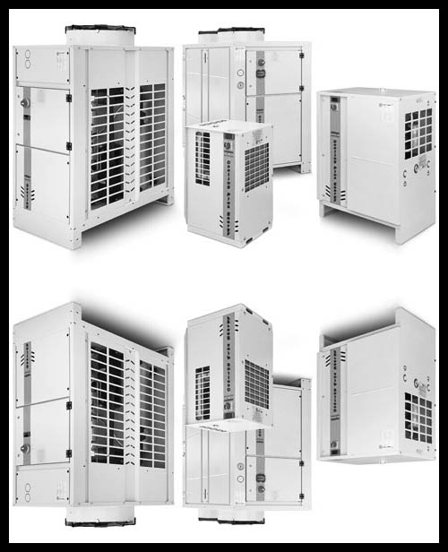
Outdoor installation (built-in capacitor)
Such units are a single monoblock installed on the street. It is convenient in that it allows you to exploit non-exploitable areas - the roof, open areas on the ground, etc. It is also a cheaper solution. At the same time, the use of water as a coolant is associated with the need to drain it for the winter period, which is inconvenient in operation, therefore non-freezing liquids are used, both new saline and traditional ones - solutions of glycols in water. In this case, it is necessary to recalculate the operation of the chiller for each specific coolant. Note that all of today's non-freezing solutions are 15-20% less effective than water. The latter is generally difficult to surpass - the high heat capacity and density of liquids make it an almost ideal coolant, if not for such a high freezing point.
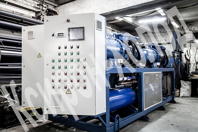
Indoor installation (remote condenser)
Here the situation is almost the opposite compared to the previous version. The refrigeration machine consists of two parts - a compressor and evaporator unit and a condenser connected by a freon route. Sometimes quite valuable areas inside the building are required, while still need outside space to accommodate the capacitor, though with significantly lower requirements both in terms of area and weight. In the chillers of the indoor unit there are no problems with the use of water. Mention is also made of the somewhat greater energy consumption of the compressor and the increased loss of pressure and temperature of freon due to the elongated path (from the chiller to the condenser), which, by the way, is also limited by the length of the compressor.
By type of capacitor:
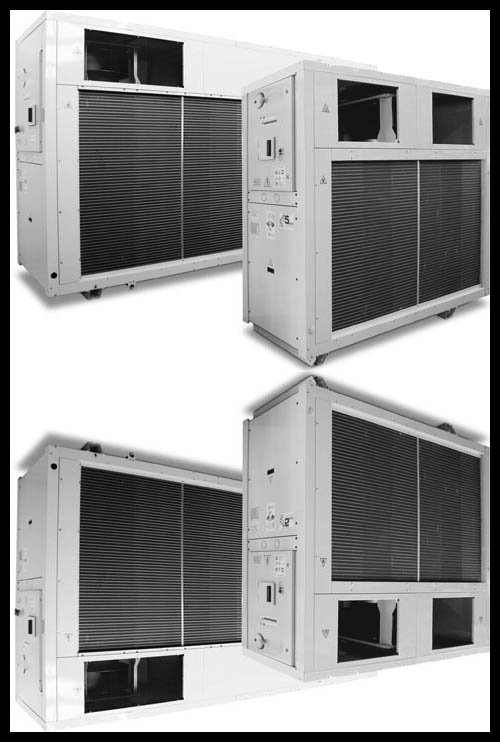
Air cooling
This is the most common option. The condenser is a tubular-fin heat exchanger and is cooled by free outside air. It is both cheap and easy to design, install and operate. Perhaps a minus can be called only the large dimensions of the capacitor in view of the low density of air.
Water cooling
However, in some cases, water cooling of the condenser is used. In this case, the condenser is a plate, plate-fin or tube-in-tube heat exchanger. Water cooling significantly reduces the size of the condenser, and also allows for heat recovery. But the obtained heated water (about 40C) is not a valuable product, often it is simply sent for cooling in the cooling towers, again giving all the heat to the environment. Thus, water cooling is really beneficial if there is a consumer of heated water. In any case, water-cooled chillers are more expensive than air-cooled chillers, and the whole system as a whole is more complicated in design, installation and operation.
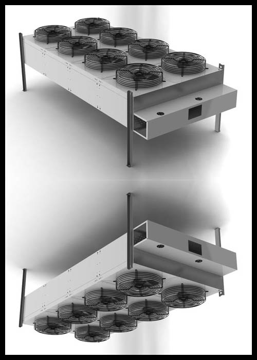
Traditionally, cooling towers are used to cool the condenser of refrigeration machines, in which water heated in the condenser is sprayed through nozzles in a stream of moving outside air, and when it is in direct contact with air, it is cooled to the temperature of a wet outside air thermometer, then it enters the condenser. This is a rather bulky device that requires special maintenance, installation of a pump and other auxiliary equipment. Recently, so-called “dry” cooling towers or condenser coolers have been used, which represent a surface water-air heat exchanger with axial fans, in which the heat of the water heated in the condenser is transferred to the air, which axial fans circulate through the heat exchanger.
In the first case, the water circuit is open, in the second case it is closed, in which it is necessary to install all the necessary equipment: a circulation pump, an expansion tank, a safety valve, and shutoff valves. To prevent freezing of water during operation of the chiller in cooling mode at negative outside temperatures, the closed loop is filled with an aqueous solution of non-freezing liquid. With water cooling of the condenser, the condensation heat is also uselessly lost and contributes to thermal pollution of the environment. If there is a heat source, such as a hot water supply system or a production line, it may be useful to use the heat of condensation during the cold period.
By type of execution of the hydraulic module:
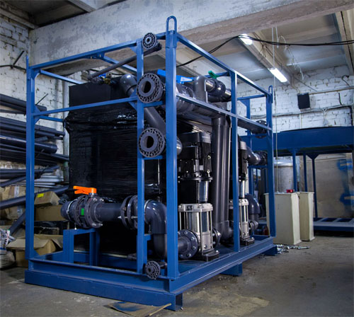
With integrated hydraulic module
Chillers of this configuration are a monoblock, which includes a pump group and, as a rule, an expansion tank. Obviously, manufacturers produce standard hydraulic modules most often of two modifications - with less and more powerful pumps that do not always satisfy the necessary requirement (usually their pressure may simply not be enough). In addition, the built-in hydraulic module in outdoor chillers will be located on the street, which can cause problems in winter - the non-freezing coolant can thicken and in the first seconds of operation the pumps are not able to overcome its viscosity and do not start. On the other hand, there is no need to look for a place for a pumping station, think through its layout, etc. plus there are no problems with automation - these are very significant advantages of the built-in hydraulic modules.
With remote hydronic module
Remote hydraulic module is used, firstly, when the built-in power is not enough; secondly, if redundancy is necessary (note that in the built-in hydraulic modules one backup pump is allowed); thirdly, if for some reason internal installation of the pumps is desired. The system becomes flexible, and the length of the track is almost unlimited, because the pumps are also very powerful. At the same time, there are also ready-made pumping stations, which include both pumps and an expansion tank and automation and are compactly assembled on a support frame.
By compressor type:
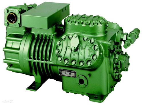
- Reciprocating Compressor
- Rotary Compressor
- scroll compressor
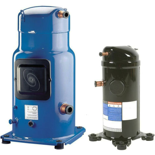
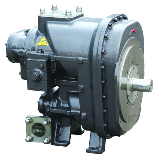
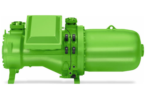
- Screw Compressor
By type of condenser fans:
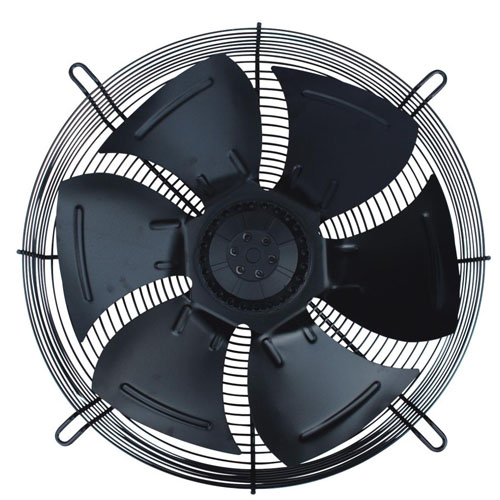
- Axial fans
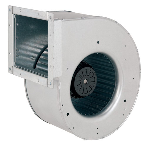
- Centrifugal fans
Chiller Options
Freecooling is a free cooling feature. Almost indispensable for chillers working in the cold season. A reasonable question arises: why use a vapor compression cycle for cooling if it’s already cold overboard. The answer comes by itself - the coolant should be directly cooled with street air. In the cold supply system, the most common temperature schedule is 7 / 12C, and, therefore, theoretically, at street temperatures below 7C it is already possible to use free cooling. In practice, due to under-recovery, the field of application is somewhat narrowed - at a temperature of 0C or lower, the cooling capacity from freecooling reaches nominal values.
Body pump - this is the “heating” mode of the chiller. The vapor compression cycle works in a slightly different sequence, the evaporator and condenser change their roles and the coolant does not cool, but heats up. By the way, we note that even though the chiller is a refrigerating machine that provides three times more cold than it consumes, it is even more effective as a heater - it will provide four times more heat than it will consume electricity. The heat pump mode is most common in public and administrative buildings, sometimes used for warehouses, etc.
Compressor soft start - an option that allows you to get rid of high inrush currents, exceeding the working by 2-3 times.
Chiller Typology
The source of cold in water-air conditioning systems is a chiller - a water-cooling chiller. There are various types of chillers depending on the method of cooling the condenser, the configuration method: monoblock or with a remote condenser, with or without a built-in hydraulic module, type of compressor, operating mode (only cooling or cooling and heating). Manufacturers are constantly upgrading their equipment based on the latest technological and design developments.
The product range of chillers manufactured in recent years has been significantly updated due to the widespread use of new, more efficient types of compressors: scroll, single-screw, twin-screw, which in the range of small, medium and large capacities are gradually replacing piston compressors. A number of chillers with an integrated hydraulic module has expanded, including a storage tank.
Lamellar and surface heat exchangers are most often used as evaporators, which made it possible to reduce the dimensions of the units and their weight. Recently, manufacturers began to release chillers on environmentally friendly freon R407C, R134a. Depending on the condenser cooling method, refrigeration units are divided into air-cooled condensers and water-cooled condensers. The most widely used chillers are air-cooled condensers, when the heat from the condenser is removed by air, often external.
This method of heat removal requires installing it outside the building or the use of special measures that provide this method of cooling. Air-cooled chillers are available in monoblock design when all the chiller elements are in one unit, and chillers with a remote condenser, when the main unit can be installed indoors, and the condenser cooled by outside air is located outside the building, for example, on the roof or in the yard . The main unit is connected to an air condenser installed outside the building with copper freon conduits.
Monoblock chillers
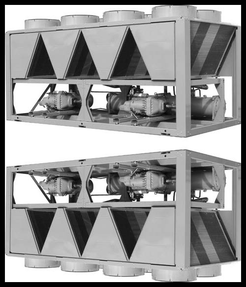
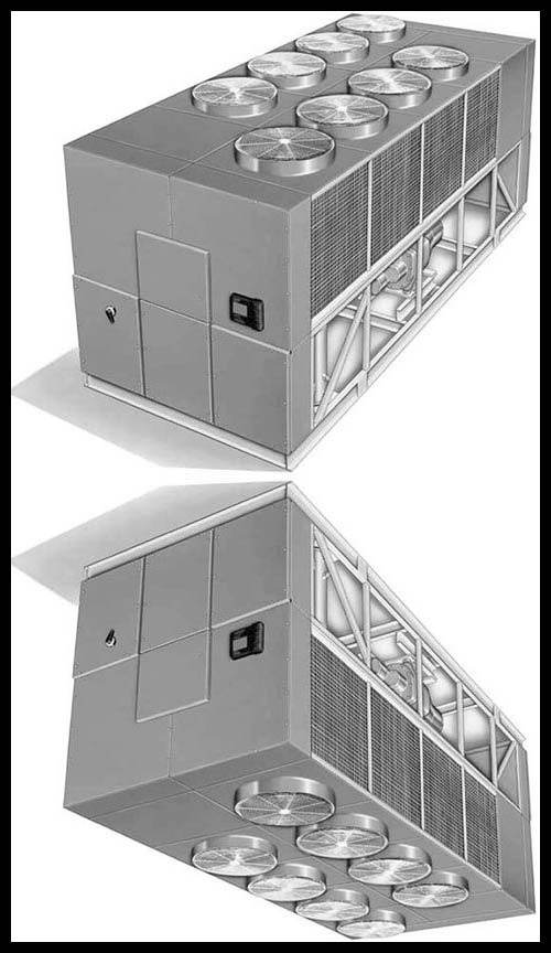
Chillers with axial fans
Monoblock chillers are available with axial fans and centrifugal fans. Axial fans cannot work on the ventilation network, therefore, chillers with axial fans should only be installed outside the building, while nothing should interfere with the air flow into the condenser and its discharge by the fans. Axial fan chillers can be manufactured in various versions: 1 - standard, 2 - with full heat recovery, 3 - with partial heat recovery, 4 - for cooling an aqueous non-freezing solution of ethylene glycol in the operating temperature range from + 4 ° C to -7 ° FROM.
It is possible to produce a chiller with an additional method of regulating cold output. With the versions of chillers 1, 3, the heat of condensation is transferred to the outside air and is irretrievably lost. With the versions of chillers 2 and 4, additional shell-and-tube heat exchangers are installed that duplicate the condenser completely in version R (using 100% condensation heat to heat water) or partially (using 15% condensation heat to heat water).
In option 4, an additional shell-and-tube condenser is installed on the discharge line after the compressor in front of the main air condenser. Chiller configuration can be: ST-standard; LN - with reduced noise level, which is achieved by the device of a sound-absorbing casing for the compressor and lowering the rotation speed of the axial condenser fan in comparison with the standard configuration; EN - with a significant reduction in noise level, which is achieved by installing a sound-absorbing casing for the compressor, increasing the living area of the condenser for air passage and lowering the rotational speed of the axial fan, as well as installing the compressor on spring anti-vibration mounts, using flexible inserts on the discharge and suction pipelines of the refrigeration unit contour.
The requirements for the sound power level created by a working chiller with axial fans when installed outside the building may not be very high if there are no special requirements for the noise level in the building where this building is located. If such restrictions exist, it is necessary to calculate the sound pressure level in the room of the noise emitted by the chiller, and if necessary, use chillers of a special configuration
.
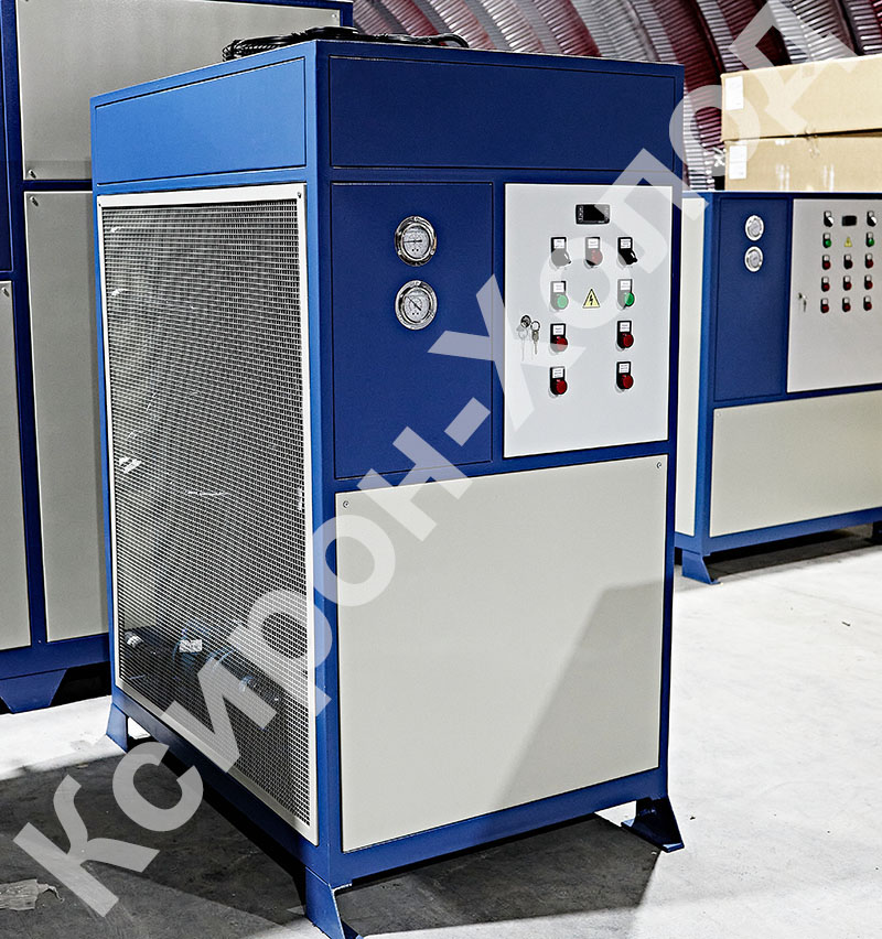
Chillers with centrifugal fans
Centrifugal fan chillers are designed for indoor installation. The main requirements for these units: compactness and low noise level associated with indoor installation. This type of chiller uses centrifugal fans with a low rotation speed, most of the sizes of small and medium capacity have a scroll compressor, which is characterized by low noise level, in sizes with a sealed piston compressor it is placed in a special soundproof casing. The side panels of the casing of such chillers have a sound-absorbing coating from the inside, along with the standard ST configuration, low noise SC configuration, where a semi-hermetic piston compressor is placed in a noise-absorbing casing and there are flexible inserts on the discharge and suction pipelines of the refrigeration circuit.
When choosing this type of chiller and its placement, it is necessary to ensure a free supply of cooling air to the chiller and the removal of air heated in the condenser. This is done with the help of suction and discharge ducts, and a ventilation network is formed consisting of a centrifugal fan, an air heater (chiller condenser), ducts, intake and exhaust ventilation louvres. The dimensions of the latter are selected based on the recommended air velocities in the cross-section of the grilles and air ducts.
It is necessary, on the basis of aerodynamic calculation, to determine the pressure loss in the ventilation network. Pressure losses in the ventilation network must correspond to the pressure developed by the centrifugal fan, with the value of the air flow cooling the condenser. If the pressure of the centrifugal fan is less than the pressure loss in the ventilation network, it is possible to apply a more powerful electric motor to the centrifugal fan by special order. Ducts must be connected to the chiller using flexible inserts so that vibration is not transmitted to the ventilation network.
Chiller Performance
Depending on the capacity, the chillers are equipped with three types of compressors: scroll compressors for low (recently shifted towards medium) capacity, single-screw compressors for medium and high capacity twin-screw compressors for medium capacity, hermetic piston compressors for low capacity and semi-hermetic piston compressors for average performance. Scroll and screw compressors as more effective in a certain range of performance compared to piston compressors gradually replace the latter. Chillers are available in two versions: working only in the chiller mode and working in two modes: the chiller and the thermal one. In air-cooled chillers, which provide for operation in the heat pump mode, cooling cycle reversal is provided, in water-cooled chillers, water circuit reversal is provided.
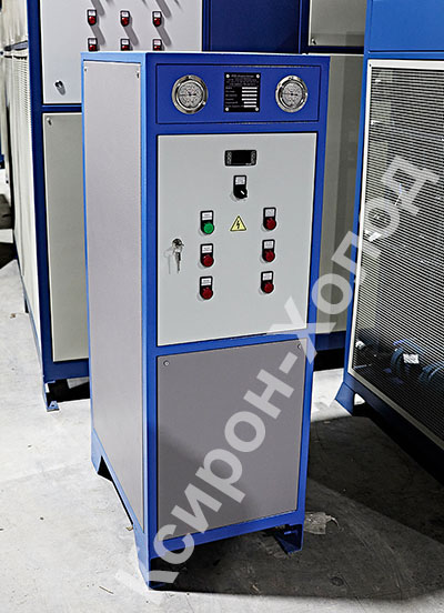
Unit diagram with integrated hydraulic module
In the embodiment, the chiller unit includes: a circulation pump on the return pipe, a membrane expansion tank, a safety valve for water, a drain valve, a water filling unit, a pressure gauge, and a differential pressure switch.
Energy-saving technologies in chillers
When developing modern climate control equipment, special attention is paid to the problem of energy conservation. In Europe, the amount of energy consumed by the equipment during the annual operation cycle is one of the main criteria for making a decision when considering proposals submitted for tender. Today, a significant potential for improving energy efficiency is the development and creation of climate technology, which is able to cover the load schedule as accurately as possible under constantly changing working conditions. For example, according to research conducted by Clivet, fluctuations in the average load on the air conditioning system during the season are up to 80%, while working at full capacity is needed only a few days a year.
At the same time, the daily schedule of thermal excesses is also uneven with a pronounced maximum. Traditionally, in chillers with a capacity of 20–80 kW, two identical compressors are installed and two independent refrigeration circuits are made. As a result, the unit is able to operate in two modes at 50% and 100% of its rated power. The new generation of chillers with refrigerating power from 20 to 80 kW allows for three-stage capacity control. In this case, the total refrigeration capacity is distributed between the compressors in the ratio of 63% and 37%.
For new generation chillers, both compressors are connected in parallel and operate on the same refrigeration circuit, that is, they have a common condenser and evaporator. Such a scheme significantly increases the energy conversion coefficient (KPI) of the refrigeration circuit when operating with a partial load. For such chillers, at 100% load and outdoor temperature 25 ° С KPI = 4, and when operating at 37% KPI = 5. Considering that 50% of the time, the chiller operates with a load of 37%, which gives significant energy savings.
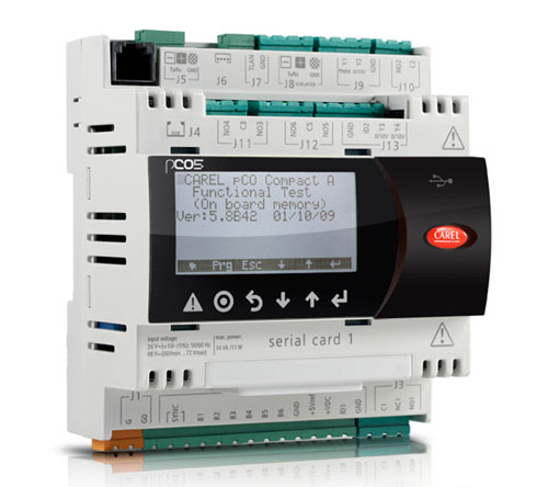
Microprocessor controllers
For effective implementation of the new solution, microprocessor controllers are installed on the chillers, which allow:
- control all operating parameters of the equipment;
- adjust the set value of the water temperature at the outlet of the chiller in accordance with the parameters of the outdoor air, technological processes or commands from a centralized control system (scheduling);
- select the optimal power control step;
- in case of real need, quickly and efficiently perform a defrost cycle (for models with a heat pump).
As a result, minimization of short-term compressor starts automatically occurs, optimization of compressor operation time and adjustment of water parameters at the outlet of the chillers in accordance with real needs. As the tests showed, on average, only 22 compressors turn on during the day, while the compressors of conventional chillers turn on 72 times.
The average annual KPI of the chiller reaches 6, and the energy saving, when using modern chillers instead of the usual ones, is 7.5 kW • h per 1 m2 of the area of the serviced object per season, or 35%. Another important advantage provided by the use of new chillers is that the need to install bulky storage tanks disappears, and the circulation pump built into the chiller body eliminates the need for an additional pump station.
Energy Efficient Compressors
As is known, the type of compressors used is of great importance for the accuracy of the execution of the chiller load schedule. Traditionally, high-capacity chillers used piston or screw compressors. A piston compressor has a large number of moving parts and, as a result, low efficiency due to large friction losses. During operation of reciprocating compressors, a high level of noise and vibration occurs, and there is also a need for their regular maintenance. Screw compressors, in turn, have a complex structure, and, as a result, a very high cost. The production of screw compressors is unprofitable.
Maintenance of such compressors is laborious and requires highly qualified personnel. In recent years, new SCROLL compressors have appeared on the market, which are devoid of the characteristic disadvantages of reciprocating and screw compressors. Scroll compressors have high energy efficiency, low noise and vibration and are maintenance free. This type of compressor is simple in design, very reliable and, at the same time, inexpensive. However, the performance of Scroll compressors, as a rule, does not exceed 40 kW.
The use in modern chillers of many small but very reliable compressors such as Scroll, as well as several refrigeration circuits, made it possible to obtain a very “maneuverable” chiller, which is capable of delivering the required refrigerating power with high accuracy. Obviously, the use of such a chiller makes it unnecessary to install a pump station, and a wide selection of pumps of different capacities built into the chiller body solves all issues related to the circulation of chilled water. Of particular note are the very small inrush currents of the new equipment. After all, the launch of small Scroll compressors with low power consumption occurs alternately, in accordance with the increase in load on the unit.
For all chillers of the latest generations, a modern microprocessor control system allows you to adjust the set value of the water temperature at the outlet of the chiller in accordance with the parameters of the outdoor air, technological processes or commands from a centralized control system (scheduling). From an economic point of view, the use of a large number of Scroll compressors and the installation of an integrated circulation pump instead of a separate pump station is more profitable than the use of expensive, powerful and complex semi-hermetic compressors.
Advantages and disadvantages of chillers
Benefits
Compared to split systems in which gas refrigerant circulates between the chiller and local units, chiller-fan coil systems have the following advantages:
- Scalability. The number of fan coil units (loads) on the central chiller (chiller) is practically limited only by its productivity.
- Minimum volume and area. The air conditioning system of a large building may contain a single chiller that occupies a minimum volume and area, the facade remains unchanged due to the absence of external air conditioning units.
- Almost unlimited distance between the chiller and fan coils. The length of the lines can reach hundreds of meters, since with a high heat capacity of the heat-transfer fluid the specific losses per linear meter of the route are much lower than in systems with gas refrigerant. < / li>
- Wiring cost. For the connection of chillers and fan coils, ordinary water pipes, shutoff valves, etc. are used. Balancing water pipes, that is, balancing the pressure and water flow rate between individual fan coils, is much simpler and cheaper than in gas-filled systems.
- Safety. Potentially volatile gases (gas refrigerant) are concentrated in the chiller, which is usually installed in the air (on the roof or directly on the ground). Pipe wiring accidents inside the building are limited by the risk of a flood that can be reduced by automatic shut-off valves.
Disadvantages
- Chiller-fan coil systems, in the strict sense, are not ventilation systems - they cool the air in every air-conditioned room, but do not affect the air circulation. Therefore, to ensure air exchange, the chiller-fan coil systems are combined with air (roof) air conditioning systems, the chillers of which cool the outside air and supply it to the premises via a parallel forced ventilation system.
- Being more economical than roof systems, chiller-fan coil systems certainly lose in cost to VRV and VRF systems. However, the cost of VRV-systems remains significantly higher, and their marginal productivity (volumes of refrigerated rooms) is limited (up to several thousand cubic meters).
- Some aspects of refrigeration design
- The chiller is overall (all three dimensions noticeably exceed a meter, and the length can exceed 10m) and heavy (up to 15 tons) equipment. In practice, this means the almost unconditional need for the use of unloading frames to distribute the mass of the chiller over a large area with the choice of acceptable support points. Standard frames are far from always suitable for each specific case, therefore, most often, special design is required.
- The VMT-Xiron chiller has 1-4 compressors, 1-12 fans, 1-2 pumps, which causes a whole gamut of negative vibrations, therefore, the chiller is installed on vibration mounts of the corresponding load-bearing capacity, and all pipelines are connected through vibroinserts of the corresponding diameter.
- As a rule, the connecting diameters of pipelines of the chiller are smaller than the main pipe (usually one, sometimes two sizes), so a transition is required. It is recommended to install a vibration insert directly at the chiller and immediately after - a transition. Due to significant hydraulic losses, it is not recommended to remove the transition from the unit.
- In order to avoid clogging of the evaporator from the coolant at the inlet to the chiller, it is mandatory to install a filter.
- In the case of an integrated hydraulic module, a check valve is required at the outlet of the chiller to prevent water from moving against the design water.
- To regulate the forward and reverse flows, a jumper between them with a differential pressure regulator is recommended.
- Finally, the documentation should always pay attention to which coolant the data are for. The use of non-freezing coolant by an average of 15-20% reduces the efficiency of the cooling system.
Hydraulic diagram of the chiller, hydraulic module
The operation chart of the chiller with an air condenser and a winter start-up system (monoblock design, without hydraulic module)
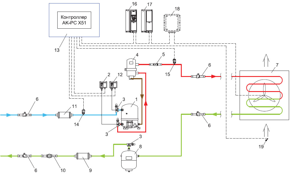
Specification - Danfoss compressor
- High pressure switch КР
- Shut-off valve Rotolock
- Differential valve NRD
- KVR condensation pressure regulator
- Air-cooled condenser
- Linear receiver
- Rotolock shut-off valve
- Filter drier DML
- Sight glass SG
- EVR solenoid valve
- Coil for Danfoss solenoid valve
- Thermal control valve TE
- Solder plate evaporator type B (Danfoss )
- Filter drier DAS / DCR
- Low pressure switch KR
- Shut-off valve Rotolock
- Date AKS temperature probe
- FQS fluid flow switch
- Electrical panel
The circuit was developed and provided by Danfoss
Chiller operation scheme with external air condenser and winter start-up system (without hydraulic module)
Specification - Danfoss compressor
- High pressure switch KR
- Rotolock shut-off valve
- OUB oil separator
- Valve non-return NRV
- Differential valve NRD
- Condensing pressure regulator KVR
- GBC ball valve
- Air-cooled condenser
- Ball valve GBC
- Non-return valve NRV
- Linear receiver
- Shut-off valve Rotolock
- Filter drier DML
- Glass sight SG
- Solenoid valve EVR
- Coil for Danfoss solenoid valve
- Thermostatic valve TE
- Evaporator plate th soldered type B (Danfoss)
- Filter drier DAS / DCR
- Low pressure switch KP
- Shut-off valve Rotolock
- Temperature sensor AKS
- FQS fluid flow switch
- Electrical switchboard
The circuit was developed and provided by Danfoss
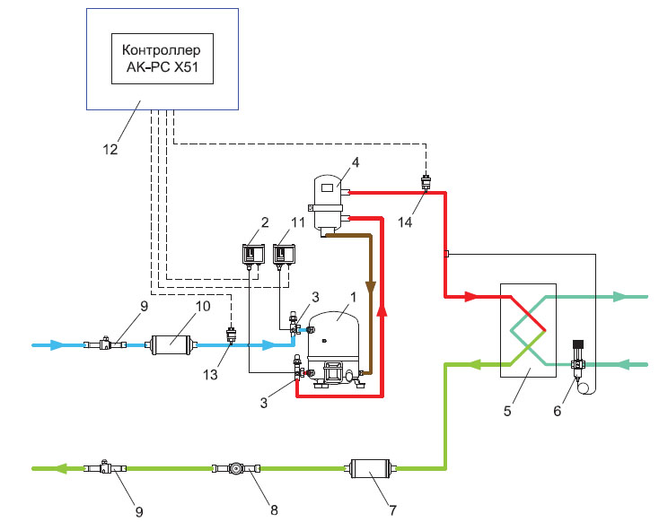
Chiller operation diagram with a water-cooled condenser and condensing pressure control

Specification - Danfoss compressor
- KP high pressure switch
- Rotolock shut-off valve
- Water-cooled condenser plate brazed plate type B (Danfoss)
- Water-control valve WVFX
- Filter drier DML
- Inspection glass SG
- Solenoid valve EVR
- Coil for Danfoss solenoid valve
- Thermal control valve TE
- Brazed plate evaporator type B (Danfoss)
- Filter drier DAS / DCR
- Low relay KP pressure
- Shut-off valve Rotolock
- Temperature sensor AKS
- Liquid flow switch FQS
- Electrical panel
Designed and provided by Danfoss
What is a fan coil: how it works and how to choose a device
A fan coil is an indoor unit of a chiller-fan coil type air conditioning system that can cool or heat the air entering it. It is used to maintain the necessary indoor climate throughout the year. This article discusses the principle of operation of such devices, their varieties, as well as the main pros and cons.
How Fan Coils Work
Fancoil, which is also called a fan coil, consists of two main elements: a heat exchanger (radiator) and a fan. Many models also have a coarse filter - it prevents dust and dirt from entering the body. The equipment should be located in the room and connected to the chiller (machine, cooling or heating liquid for transferring thermal energy) using a network of pipelines.
By the principle of operation, the fan coil is very similar to the indoor unit of the split system. The main difference is the coolant: instead of the refrigerant, the fan coil uses ordinary water or a non-freezing solution. The liquid cools or heats the incoming air, which is brought to the desired temperature and returned to the room. The resulting condensate is diverted to the street or sewer using a pump.
As in the case of heating radiators, often several fan coils are often installed in the same room at once - the required number depends on the power of the devices and the area of the room. In addition, they can be connected to the supply ventilation, which allows the use of devices in a mixed mode (to mix the air received from the inside with fresh air).
Temperature control is performed using the electronic system control unit, temperature sensors and various valves. Complex air conditioning systems also use central air conditioners, which are responsible for cleaning and humidifying the incoming air.
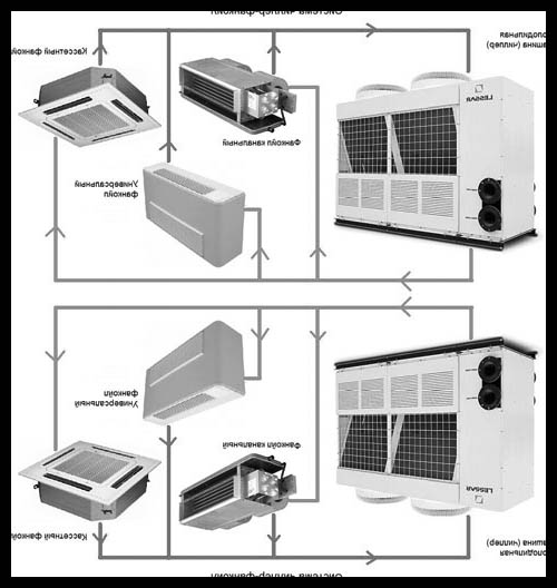
Types of chiller-fan coil systems
There are two main types of chiller-fan coil systems:
- Single-zone system . It is mainly used for servicing large areas with uniform heat distribution, since all single-circuit fan coil units connected to it are heated and cooled at the same time.
- Multizone system . It uses fan coil units with double-circuit heat exchangers, which allows to separate the supply of cold and hot water. Devices in such a system can simultaneously provide different air temperatures in different rooms.
Varieties of fan coils
All fan coil units operate on the same principle - devices differ only in installation method. Four main types of fan coils can be distinguished:
- Cassette;
- Floor standing;
- Wall mounted;
- Channel.
Each of these types is described in detail below.
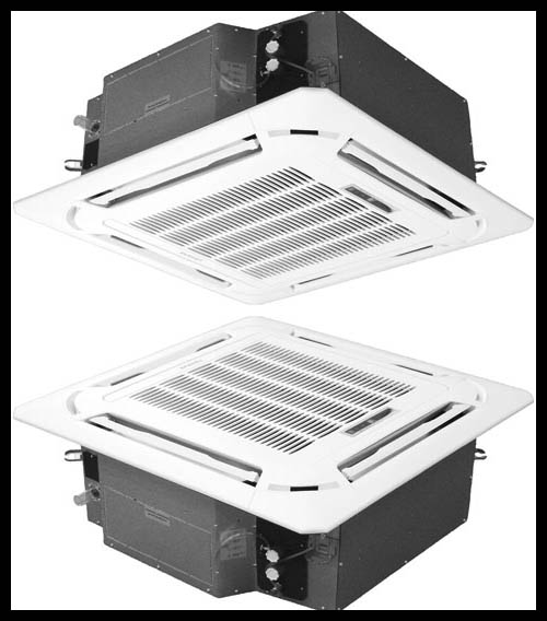
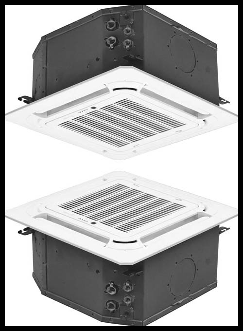
Cassette fan coils
This type of device is often used in air conditioning systems for offices or retail spaces with high false ceilings, as they can be installed in them. Cassette fan coils are available in the following varieties:
- Single-threaded (air is discharged from the device in one direction);
- Dual-flow (two air flows in different directions from the device);
- Four-flow (models of this type produce four air flows, which makes them the best choice for air-conditioning of large areas).
Floor fan coils
The simplest in terms of installation type of fan coil with an external housing that attaches to the floor. The most effective location for the floor unit is in front of the windows, as the air flows coming from it are directed to the ceiling, creating an effective thermal curtain. Such fan coil units can be supplied with both integrated devices and remote controls.
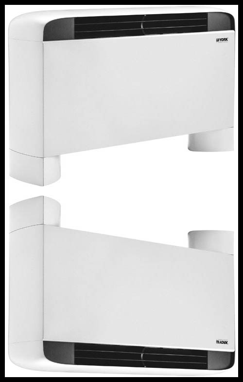
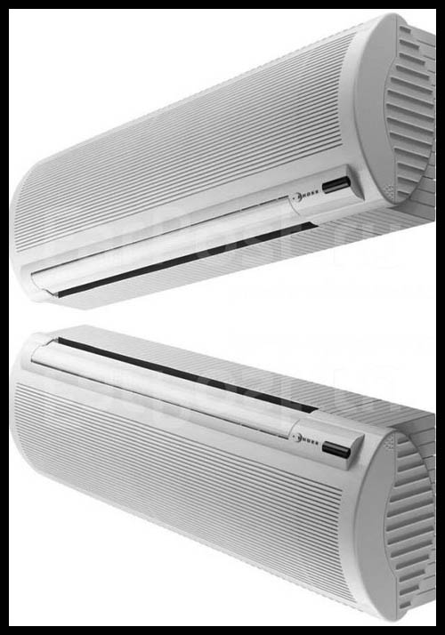
Wall mounted fan coils
Like floor units, wall mounted fan coils are protected by decorative enclosures. They are quickly mounted on a wall in any suitable place of the room. Most often they are installed above the door. Almost all wall units are equipped with convenient remote controls.
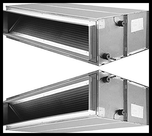
Channel Fan Coils
Unlike wall or floor units, channel fan coil units do not have a housing - they are installed directly in the ventilation shafts. Devices of this type are mainly used for cooling or heating air in spacious rooms that need high-performance air conditioning systems (trading floors, cinemas, entertainment centers, production shops, etc.).
How to choose a fan coil
When choosing a fan coil, the following device parameters should be considered:
- Type (cassette, floor, wall or channel);
- Power (the minimum indicator in watts can be obtained by multiplying the area of the air-conditioned room by 100);
- Energy efficiency (relevant only for large air conditioning systems, since fan coils consume quite a bit of electricity);
- Noise level (it is recommended to use devices with quiet fans, the noise level of which does not exceed 60 decibels).
Advantages and disadvantages of fan coils
Chiller-fan coil systems are popular due to a number of advantages compared to traditional split systems. Among the advantages can be identified:
- Scalability. The distance between blocks in split systems does not exceed 15 meters due to the refrigerant used in them. At the same time, the distance between the chiller and the fan coil can exceed hundreds of meters, which makes it easy to expand the system if necessary.
- Versatility. Unlike air conditioners in standard split systems, fan coils are able to function non-stop throughout the year.
- Safety. Fan coil fluids are much safer compared to the gas refrigerant used in split systems.
Unfortunately, fan coils also have disadvantages. These include:
- The large size of the system. Due to the impressive size of the chiller-fan coil system, its installation is only advisable in spacious buildings.
- Poor filtration quality. The filters for air purification built into fan coil units do their job much worse than their counterparts in split systems.
- High installation complexity. Due to the large size and weight of the chiller-fan coil systems, it takes a lot of time and effort to install them.
Drikulers: features and types of devices
A dry cooler, or dry cooling tower, is a fan apparatus used to cool the coolant by blowing it with street air. It is used both in small air conditioning systems - the fancoil chiller, and in large industrial enterprises. On this page you can find basic information about drivers, as well as a list of the most famous manufacturers of these devices.
The principle of operation of the drycooler
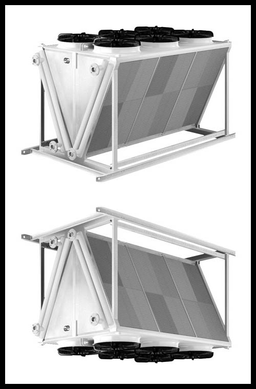
The design of the drycooler includes three main components:
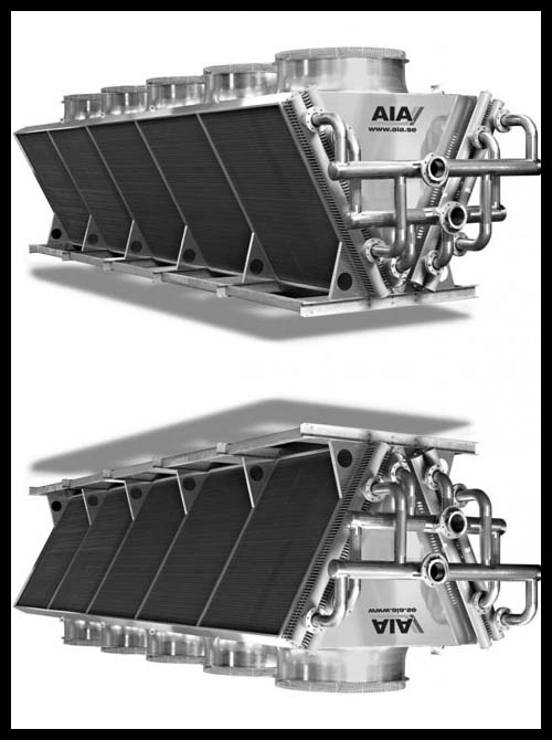
- Plate heat exchanger. It can be V-shaped, horizontal or vertical. Most often made from aluminum or copper. Efficient heat transfer is ensured by the high number of fins, and, as a result, the large surface area of the heat exchanger.
- One or more fans. Most drycoolers are equipped with axial cooling impellers with a radius of 200 to 350 mm. In large devices with V-shaped heat exchangers, fans with a diameter of up to 1000 mm are allowed. In addition, centrifugal fans can be used in high-performance industrial cooling systems.
- Protective and regulating automatic equipment responsible for maintaining the required temperature of the coolant and changing the speed of the fans.
- The heated coolant (ordinary water or non-freezing solution) is fed to the inlet of the drycooler, where its temperature drops to the temperature of street air. The cooling level can be adjusted by changing the fan speed. The fluid is supplied using a circulation pump. After that, the coolant is fed back to the equipment to be cooled, and then the cycle repeats.
Advantages and disadvantages of dry cooling towers
Drycoolers have several advantages. These include:
- High energy efficiency;
- Environmental safety (the energy carrier circulates in a closed loop, and, as a result, does not evaporate, keeping the humidity level at the same level);
- Easy installation, operation and maintenance;
- Low cost of equipment;
- Ease of scaling (new blocks are easily added to the existing cooling system);
- When working with drycoolers, you can use any non-freezing solutions.
At the same time, drycoolers have several significant drawbacks:
- The performance of the devices depends on the outdoor temperature (there may be problems during peak temperatures in winter and summer);
- Drycoolers use more energy than standard evaporative cooling towers.
Scope of Drycoolers
Due to their good energy efficiency and low cost, drycoolers are popular in a number of applications. They can work both independently and as auxiliary equipment together with refrigeration units. In particular, dry coolers are used:
- In production requiring large volumes of coolant;
- In industry for cooling coolants in refrigeration and injection equipment, as well as heat removal from extruder engines, machine tools and generators;
- In construction to reduce the temperature of refrigeration units and generators;
- For free cooling of air in public and industrial buildings (freecooling).
- A large assortment of models and configurations of drycoolers allows you to choose a unit with suitable characteristics for any operating conditions, so every year their popularity only increases.
|