CHILLED WATER FOR HVAC APPLICATIONS
The main vapor compression cycle, when applied directly to the workers in the building cooling, called direct expansion (DX) systems of cooling. This link comes from the fact that the building of the air in the room that is to be cooled passes directly over refrigerant evaporator without a secondary refrigerant is used. Although these cooling systems are widely used in residential, commercial and industrial applications, they have application capacity, performance and limit their use in large and complex HVAC applications. For these applications, the use of chilled water system is dictated. Typical applications for chilled water systems include large buildings (offices, laboratories and others) or multibuilding campuses, where it is desirable to provide cooling from a Central facility.
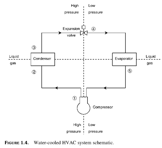
As shown in Fig. 1.4 typical water-cooled HVAC system consists of three heat transfer loops:
Loop 1 Cold air extends to one or more air-handling units for rooms inside the building. Sensible heat of profits, including from the heat temperature-driven transfer through the building envelope; direct solar radiation through the window; infiltration; and the internal heat by people, lighting and equipment, absorbed cold air, increasing its temperature.
Latent heat, moisture added to the space by air infiltration, people, and equipment, also absorbed by the cold air, lifting her specific humidity. The resulting space temperature and humidity condition is exact balance between sensible and latent heat profits and the possibility of entering the cold air to absorb those heat gains.

Cycle 2 distributed air is returned to the unit, mixed with the required amount of outdoor air for ventilation, and then directed through the coil where cooling water is used to extract heat from the air, reducing its temperature and humidity, so it can be distributed once more space.

As chilled water passes through a cooling coil in the slipstream, heat extraction process causes the water temperature to rise. The temperature of chilled water, leaving the cooling coil (chilled water return) will 8-16F warmer than the water temperature at the inlet (chilled water supply) on the design load. This temperature difference (range) sets a stream requirements via the relationship shown in the equation. 1.1.
Fchw = Q/ (500 X-band) (1.1)
where Fchw = flow rate of cooling water (gpm), Q=, the overall system cooling load (BTU/HR), the Range of = the temperature increase of the cooling water (F), 500 = conversion factor (Btumin/gallonFHR) (1 BTU/lbF X 8.34lb/gallon X 60 min/HR).
Warm return chilled water enters the water cooler, where it is cooled to the desired supply temperature chilled water through the transfer of heat extracted from the premises of the primary refrigerant. This process is obviously not free as the compressor should work with refrigerant for cooling will happen, and, thus, must consume energy in the process. Since most chillers refrigerant is cooled compressor energy as heat is added to the building heat and both must be rejected through the condenser.
Cycle 3 the amount of heat that is added using the compressor depends on the efficiency of the compressor. This heat of compression should be added to the thermal load of cooling water loop to establish the amount of heat that has to be rejected on the condenser heat sink, as a rule, outdoors..
|


