Centrifugal compressors
Piston compressors operating at about 24 rev s-1 have the potential of about 35 kW per cylinder using the usual Air conditioning applications. The maximum number of cylinders on one machine is 16, so it puts the maximum amount of piston machine in about 550 kW, freak, except machinery with large strokes and holes. Although one piston compressor this size is likely to be cheaper than a centrifuge from capacity, the complication of monitoring its output (cylinder unloading) may put it in a bad way in comparison with the centrifugal compressor, which may have regulatory control over his power and the consumption of cooling water temperature. Centrifugal systems are available for capacities as low as 280 kW, but they come into their own, economically speaking, at an altitude of about 500 kW, maximum-about 20 000 kW.
Whereas, piston compressor piston device, centrifugal compressor will not. If the gas flow in a piston engine lack of resources, it will continue to pump, although the quantities of small, provided that its speed is stored adequate input power for the crankshaft.
No 'dead end' state. Not so with centrifugal compressor. Rotating impeller centrifugal compressor increases the pressure of the gas flowing through their channels into force of centrifugal forces as a result of its angular velocity. Impeller speed is constant in the radial direction, but at a linear velocity in the direction at right angles to the wheel radius increases the radius gets longer.
Energy cost of gas, which rotates within the impeller, thus increases towards the periphery of the wheel. This input energy is what makes the movement of gas to the outside through the impeller against the pressure gradient, that is, from low pressure prevailing at the entrance eyes on high pressure existing at the periphery. The function body, impeller, or " snail", is converting speed, the pressure of the gas leaving the steering wheel so that the static pressure, with such efficiency as possible.
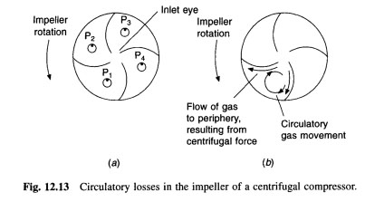
In addition to the circular movement imposed on gas impeller, gas flow, as a rule, rotate relative to the impeller. This is illustrated in Fig. 12.13(a). On an absolute basis, any specific gas particles, as a rule, do not rotate but as the wheel rotates, the particle will be rotated about the wheel. Point Pj faced with the convex side of the impeller blade initially, but later, during the rotation, labeled P4, she is faced with the concave side of the previous banana blade. The effect of this is to produce a circulatory motion of the gas inside the wheel, as shown in Fig. 12.13(b). It can be seen that this circulatory movement helps the flow to the periphery of the wheel, produced by centrifugal force, on the concave side of the blade, but inhibits the convex side. Effect introduces losses which can be minimized with the help of wheels with narrow channels between the impeller blades.

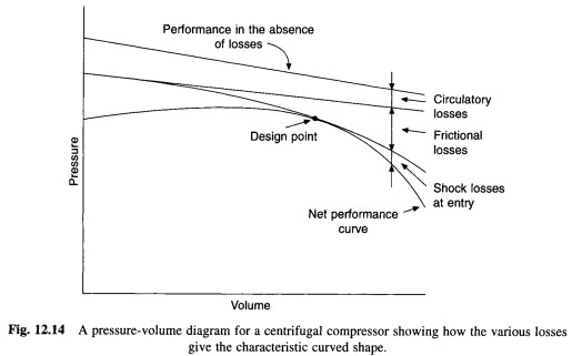
For a given compressor, running at a given speed, the pressure-volume feature almost a straight line, as shown in Fig. 12.14, if not losses occur. Losses have occurred, however. They are the circulatory loss just described, losses due to friction, and losses caused by the fact that gas at the entrance in the impeller must change direction by 90 degrees, as well as having the rotation imposed on it. These records losses can be changed by setting the vortex of gas before it enters the inlet eye of the impeller. There's a right angle of torsion for each gas flow velocity, that is, for each concrete cargo. Variable-VNA-equipped with all modern centrifugal compressors. Their position with regard to the changes balancing, which allows continuous regulation of the output with little alteration in efficiency. The intention is that the machine should be operated at design point, which involves minimal losses at maximum efficiency.
Centrifugal impeller is designed to transport gas between low suction pressure and high condensing pressure. If the condensing pressure rises, the difference between these two pressure exceeds the estimated value and the compressor pretty soon finds the task of pumping beyond its ability. Thus, whereas the reciprocating machine will continue to pump, but it is constantly reducing speed as it rises condensing pressure rate of the pump centrifugal compressor falls rapidly away. This is illustrated in Fig. 12.15(a). This behavior can occur if the suction pressure is reduced, the condensing pressure is held constant value, as in Fig. 12.15(6) shows.
This feature centrifuge performance generates this phenomenon is called 'raging'. When the pressure drop exceeds the design of the pumping ability of the impeller and flow ceases, and then changes because high condensing pressure disks of gas in the opposite direction to the bottom of the suction pressure. Pressure in the evaporator then builds up, and the difference between the high and low sides of the system decreases until it is again within the capacity of the pump impeller. The gas flow is then returned to normal direction, pressure difference, rises again, and the process repeats.
These fluctuations in gas consumption and the rapid change in pressure difference that makes his stomach. In addition to disturbing noise, which surging produces loads on the bearings and other components, wheels and engine damage may result. Constantly growing highly undesirable, but some splash it is likely occur from time to time, if carefully watch is stored at the plant. This is particularly true of plants, which operate automatically and remain for a long time unattended. The surge is likely to occur under low-load conditions (when the suction pressure is low) in combination with a high temperature of condensation.
Proper use of VNA can give a smooth power regulation to 15% or even as he claimed, up to 10 percent of the design with a full load. The high heads necessary for air conditioning applications can be developed in two ways: either the impeller fast enough to give a high speed and wanted, or using multistage compressor. High tip speed can be obtained using large diameter wheels, but if their diameters are excessively large, structural and other obstacles.
 .. ..
|


 ..
..