Simple vapour compression cycle
Pair compression cycle used for cooling in preference to gas cycles; using latent heat allows for much greater amount of heat to be recovered refrigerant flow. This makes equipment as compact as possible.
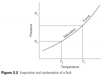
Liquid to boil and evaporate - change between the liquid and gaseous state at a temperature, which depends on the pressure within its freezing point and the critical temperature (see Fig. 2.2). In boiling he should get the latent heat of evaporation and condensation in the latent heat is transferred.
The heat is in a liquid state at low temperatures and pressures, providing the latent heat to make it to evaporate. The pair, then automatically he is compressed to high pressure, the saturation temperature corresponding to its latent heat may be refused, so he changes back into a liquid. The cycle is shown in Fig. 2.3 . The effect of cooling of the heat-carrier in the process of evaporation, which is the change in enthalpy between liquid and vapour, leaving испаритель.
To investigate this process more closely, refrigerating engineers use pressure-enthalpy or P-h chart (Fig.
2.4) . This diagram is a convenient way of describing the liquid and gas phases of matter. On the vertical axis, pressure P, and horizontally, h, enthalpy. The saturation curve defines the boundary of a pure liquid and pure gas or vapor. The region showed vapor, liquid superheated steam. The region is marked by fluid, supercooled liquid. At pressures above the upper curve, there is no distinction between liquid and vapour. Above this pressure gas cannot be liquefied. This is called the critical pressure. In the area under the curve, i.e. a mixture of liquid and vapor.
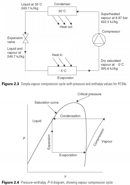
Simple vapour compression cycle is superimposed on the P-h chart in Fig. 2.4. The process of evaporation or evaporation of the coolant is a constant pressure process and hence it is a horizontal line. In the process of compression of energy used for compression of vapor turns into heat and increases its temperature and enthalpy, so that at the end of the vapor compression state in the superheated charts and outside the saturation curve. A process in which heat of compression raises the enthalpy of gas called adiabatic compression. Before condensation can start vapors must be cooled. The final compression temperature is almost always below condensing temperature as shown, and, therefore, a certain amount of heat is rejected at temperatures above the temperature of condensation. This represents a deviation from the ideal cycle. The actual condensation process is presented of the horizontal lines within the saturation curve.
When simple vapour compression cycle is displayed on the temperature-entropy diagram (Fig. 2.5) , deviations from the reverse Carnot cycle can be identified by the shaded places. Adiabatic compression process continues beyond the point where the condensing temperature is reached. The shaded triangle represents the additional amount of work that can be avoided if the compression process changed to isothermal (i.e. at constant temperature) at the moment when it continues until the condensing pressure is achieved.
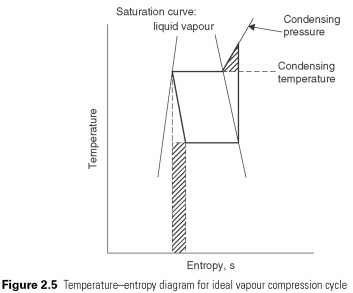
Expansion of constant enthalpy of the process. It shall be prepared in form of a vertical line on the P-h schema. No heat is absorbed or rejected during the expansion of the liquid just passes through the valve. After reducing pressure in the valve should lead to a corresponding decline in temperature of the liquid vapours flash to remove the energy for cooling. The volume of liquid, thus increases valve quantity of associated gas, which leads to its name, the expansion valve. No attempt is made to recover energy from the process of enlargement, for example. with the help of the turbine. This is the second deviation from perfect cycle. Work that could potentially be restored is represented by the shaded rectangle in Fig. 2.5.....
|


