4-way (reverse) valve
4-way valve with operating control used for heat pumps. This is called the 4-way valve, because it has four connections refrigerant pipes. Because the heat pump uses of reversible mechanical refrigeration cycle, such device is not required.
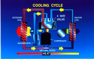
Shown here, the heat pump cooling works like any cooling system when it is in cooling mode. With 4-way valve in its correct position, the internal heat exchanger absorbs heat from the air in the room and the outdoor coil rejects heat from the outside air. Heat moves indoors to outdoors. Refrigerant circuit in 4-way valve in a way that makes it possible. In highside system is on the left side of the illustration (outdoor), while the lowside right (in the room). , Refrigerant, moving from left to right by a measuring device. Fixed-metering device is often used because it allows you to go in any direction. Agreement with two metering devices and valves is common.
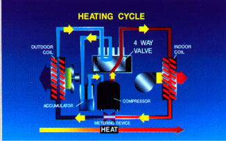
The heating mode, the 4-way valve is moved to the left of this provision.
The transition changes the direction of refrigerant flow through the system. This changes the functions of the coils.
Outdoor coil now, absorbing heat from outdoor air, while the internal heat exchanger rejects heat the air in the room. Heat moves from the great outdoors and indoors. Refrigerating cycle of "pumping" of heat into space. In highside systems currently on the right side of the illustration (indoor), while the lowside left (outdoors). The refrigerant is moving from right to left by a measuring device.
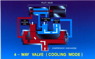
This view in the context of the 4-way valve and shows how he performs its task. Here in the right position, that should put cycle cooling in cooling mode. The pilot valve to the top of the diagram consists of two sections. The chamber on the right contains an electric coil with the pilot pin-code, which is stored in the coil when the current feed. In cooling mode, the electric coil is de-energized, so PIN extended, as shown.
In the cell on the left contains the sliding piston with three small capillaries, connecting it to the main valve. In the position shown here, the pilot valve allows the high pressure gas injection will focus on the suction line with the right capillary tube. The pilot valve of blocking high-pressure gas from the compressor discharge, trapping gas in the left end of the main valve slide. Because the pressure is higher in the left part of the slide, than the right, slide goes to the right. On these routes refrigerant gas system to provide cooling.
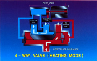
In heating mode, the pilot contactor, pulling the plunger back. This allows the low-pressure suction gas sent to the left side of the main valve slide through the left capillary tube. Because the pilot valve of blocking high-pressure gas from the compressor discharge, his traps gas on the right end of the main valve slide. A higher pressure in the right side of the slide, than on the left, so the slide is on the left. On these routes refrigerant gas to the system provides heating...
|


