Seeing The Invisible
P-H chart allows you to "see invisible". Most of the service work on the refrigerant side of the system needs to know the refrigerant conditions in different points of the system. You must know the temperature, pressure and state.
Electric temperature sensor, you can find the temperature of the refrigerant in many places in Moodle. With the temperature alone, however, you will not know refrigerant high or low pressure, or whether it is cold, saturated or superheated. If it is saturated, you will not know if it is saturated liquid, vapour, or their mixture. Because we can't see inside the system, P-H chart gives us the "eyes" we need to "see", refrigerant conditions other than temperature.
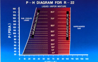
Temperature readings 40F refrigerant will not tell us, of course, other refrigerant conditions. However, if we also know that his pressure 55,3 PSIG, which is 70 PSI (55.3 PSIG + 14.7 psi = 70 psi), and we, using the supplied P-H schema, then we know that the refrigerant is in the point "E", which is superheated gas.
We can also see from this P-H chart refrigerant and contains about 10F overheating, as the saturation temperature of 70 PSI is about 30F. Our sample is 40F, which is 10F more than this (10F superheated).
P-H schemes:
- Find The Pressure That Corresponds To Any Saturation Temperature
- Allows You To Find All The Conditions Of The Refrigerant
- Use One Chart to plot the performance of All Components
- See the Work of Each Component and the Impact of Other System Components
So far we have seen that the P-H chart can be used to quickly find the pressure that matches any saturation temperature of the refrigerant. This will also allow you to find all the refrigerant conditions, when the temperature and pressure are known. The third objective of the P-H schema-plot in one circuit, the performance of all components of the cooling system. The system of the plot allows to visualize what each part of a system of reference with regard to pressure, heat capacity, and temperature of the refrigerant as it flows along. It also helps us to get a true picture of how each component works, and effect on other components of the system..
|
