A Simple Loop
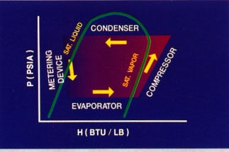
Here is a view of the refrigerant to be the story about the P-H-diagram of the overall system. This chart shows the area system in the simplest fashion with one side of the plot of the system of compliance of each of the four main cooling cycle components. Step-by-step discussion below shows the same principle in more detail. Refrigerant conditions at the inlet and outlet of each component, - he stressed.
As this area and more detailed that it should be a bit simpler than reality, because they ignore the refrigerant pressure loss of refrigerant, as well as in the evaporator and condenser. They also ignore the heat through profit and loss for the refrigerant. Even without these adjustments to our plots are reasonably accurate.
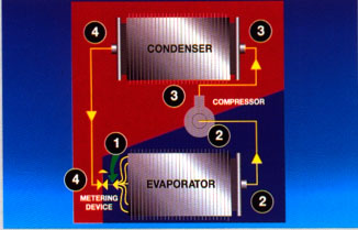
This shows how the four main components of the refrigeration cycle coincides with the cycle of the plot just shown on P-H schema. The same figures are used in a detailed'kyi, the plot that way.
Use these figures together with this simple figure, as we follow the refrigerant in the system P-H schema.
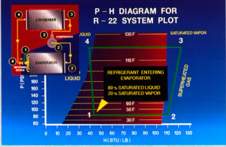
Starting at evaporator inlet (paragraph 1), the refrigerant at a temperature of saturation. This corresponds to a gauge pressure of about 69 pounds per square inch, which is the same as 83.7 PSIA (69 PSIG + 14.7 psi). The P-H chart, you can see that the refrigerant in the evaporator in this example, nearly 80% of the saturated liquid and 20% saturated vapor; this is typical not only for comfort, air conditioning systems...
|


