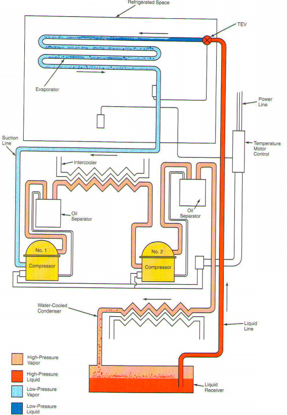
In refrigeration systems, two or more compressors are connected in series, figure 3-11. In this example, compressor 1 empties into the compressor suction в„– 2. Compressor 2, and then flows into the condenser (red light). Here vapor condenses. Liquid refrigerant (dark red) is supplied in the receiver. Refrigerant vapor not condensed between compressors. Intercooler, lowers the temperature of the steam. This type of installation, as a rule, requires the separation of oil for each compressor.
From the liquid liquid refrigerant receiver (dark red) flows to the thermostatic expansion valve. Then he enters the evaporator. In the evaporator (dark blue) refrigerant boils and absorbs heat (light blue). The evaporator, the refrigerant evaporates water returns to the compressor 1. Hence the cycle repeats. A composite system, increases the capacity of when pulling down to very low pressure (low temperature). One compressor will be difficult to achieve these pressure/temperature.
One is the temperature of the engine control manages all the engines.
Thermostatic expansion valve controls the flow of liquid refrigerant in the evaporator. Pressure balance on the outside of the cycle. Therefore, engines capable of running under load required. Composite units typically operate at a very high service requirements. Capacitors and refrigerant should be kept clean. Valves of the compressor must be in good condition.