Multistage cycles
Where the coefficient of suction, discharge pressure is high enough to cause a serious drop in volumetric efficiency or unacceptably high discharge temperature, vapour compression should be held in two or more stages.
Two-stage systems use the same refrigerant in the chain, holding in two stages. Using a separate compressor for each phase, the second phase, the movement may be adjusted to accommodate the additional load on the cooling system, lateral loads. in the intermediate pressure. Compression in two phases during one machine can be done using the multicylinder compressors. At the first stage of compression, say, 4 cylinder, and at the second stage 2-cylinder 6-cylinder machine. Hot gases from the first stage of the compressor runs through the intercooler high stage compressor, and consists of a small evaporator provided by the refrigerant from the condenser.
In addition cooling water heat exchanger can be used, or a simple injection metered quantity of liquid refrigerant from the condenser) to mix with the intermediate pressure gas.
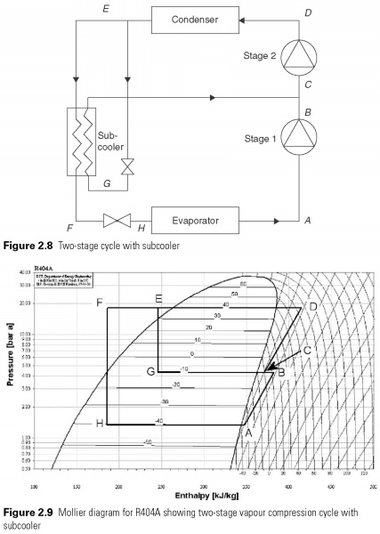
A cost-effective alternative location is shown in Fig. 2.8 and 2.9. Part of the liquid refrigerant from the condenser is taken subcooler, where the main flow expansion valve, liquid cooled, E and F, and this increases the debt of the evaporator (A-H). This cycle is more effective than one stage of the cycle, as part of the mass flow rate of compressed only at the second stage. Flash intercooler can be used instead of subcooler. All liquid is then reduced to medium pressure through suitable expansion valve. The intercooler acts as a container for the division, which flash gas generated in the process of expanding separated from the liquid. From the intercooler, flash vapor this led to a higher stage compressor, while the liquid, which was divided, further expanded and low pressure. Float valve type shown in Fig. 8.10 can be used to control admission to the intercooler.
Version two stages of the cycle, called the economizer cycle can be scrollable and винтовые compressors. On these machines, access to intermediate pressure in the process of compression via the auxiliary port on the housing allows steam subcooler impose part-way through the compression process. Only one compressor, and it is almost identical to the single-stage version, require the injection port pair. Economizer cycle is a very economical way of achieving high performance.
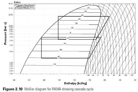
Cascade loop has two separate cooling system, one acting as a condenser to another (see Fig. 2.10). This method allows the use of different refrigerants in systems of high pressure refrigerants, such as R23 are used in the lower stage. Cycle is displayed on the same graph for convenience.
The Mollier diagrams for complex and cascading systems (Fig. 2.9 and 2.10) indicate a change in the enthalpy per kg refrigerant circulates, but it should be borne in mind that the prices of mass flows in the low and high stages differ, and this should be taken into account when calculating the power.
 .... ....
|

 ....
....