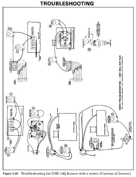
For Troubleshooting procedures, Lennox Pulse furnaces are shown in Fig. 2-20. Fig. 2-21 shows a chain of G-14 C furnace series. Note the difference in the electric circuit for the G-14 and GSR-14. Fan speed colored wires are also different departments. 40, 60, 80 and 100 after the G-14 C indicates whether it is 40,000, 60,000, about 80 000 or 100 000 BTU/h unit. Thermostat anticipation of heat is also given, for Robertshaw valve and Rogers valve. This type of electrical circuit, usually glued to the Cabinet so that it was with one whenever the need arises in Troubleshooting.
Troubleshooting flow chart is typical of those furnished with new equipment in the technical manuals furnished dealers who provide the service. After the discovery of the exact symptoms, contact other part of Fig. 2-20 to learn how to use a multimeter to check all the schemes to see if the exact cause of the problem can be determined.
ne size-full wp-image-86" title="troubleshooting-GSR-14Q" src="//www.ref-wiki.com/img_article/troubleshooting-GSR-14Q.jpg" alt="" width="450" height="582" />