Flooded-ceiling fan
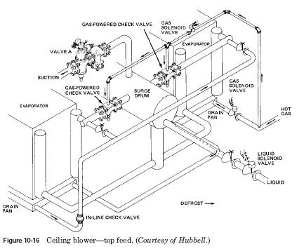
Top hot gas feed Fig. 10-16 shows a modification of the system is shown on Fig. 10-15. In the system shown in Fig. 10-16, top-fed hot gas defrost forces evaporator liquid directly on the bottom of a large separator. Defrost knob (valve), normally open, off during defrost act as a relief to the regulator. To minimize the heating of ammonia, which accumulates in the breather during defrost thermostat bulb should be used to experience the increase of temperature in the bottom of the header. The thermostat can be used to complete the defrost cycle. Again, with a gas engine shut-off valve to isolate the evaporator from the separator until the gas pressure disabled. 
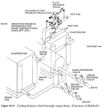
Hot gas supply through the breather Fig. 10-17 shows a simple defrosting. This is the installation of the cooling system shown in Fig.
10-16. However, as evaporator and separator are emptied during the defrosting that requires the use enough liquid to protect the compressor. In this system the pilot solenoid valve, coupled with reverse pressure regulator limits the pressure in the system. This allows a simple solenoid valves to control the speed of the line of relief. 
..
|


