CONSTRUCTION OF AIR COILS
The number of air-cooling coil in operation in industrial refrigeration plants significantly exceeds the amount of liquid cooling evaporators. Before explaining the performance of the air, coil, physical features several types of industrial cooling coil will be presented. The main components of the air coil pipes, tubes, sheets, fins, and drain pan.
The tube. Tubes, pipes, enclosing a refrigerant. The most common materials used for pipes of carbon steel, copper, aluminum and stainless steel. If ammonia refrigerant any of the four materials, except for copper and may be used, and most Halocarbon systems are used coil with copper tubes. The most common sizes of steel coil pipes for ammonia 3/4, 7/8 and 1, although 5/8 inch pipes are also used. For small chladone coils, 1/2-in copper pipes are sometimes used.
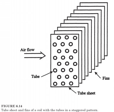
Tube sheets. At the end of each coil heavy plate supports tube with holes through which the pipe to go through. Picture of these holes to determine whether the pipes are in-line or staggered. Coil elements Fig.
6.14 depict a checkerboard pattern for pipes. Coil with staggered-fin pattern is slightly improved heat transfer, but at the expense of a slight increase in air pressure.
The fins can be applied wrap strip of metal in a helical fashion around the tube and then pasting it into the tube. Much more likely, however, is to use a plate or flat ribs, as indicated in Fig. 6.14. Materials available for these fins are the same as for pipes, as well as typical combination of pipe/ribs materials:
- copper tube/aluminum fin for halocarbons air-cooling coil
- aluminum tube/aluminum fin for Halocarbon or ammonia air-cooling coil
- carbon steel, pipes/carbon steel fin for air-cooling coil using ammonia, freon, refrigerating fluids or water in the pipes
- stainless steel pipe, stainless steel fin, when the special cleaning provisions are required on the air side
Stainless steel is usually used only for very low temperatures, where there is a corrosive atmosphere, or whenever periodic cleaning is necessary. The thermal conductivity of less than carbon steel, which itself is about one fourth of that of aluminium. The cost of stainless steel coil, maybe five or more times that of steel coil of comparable size.
Application of coil, in particular, whether it becomes matte, largely determine the distance between the ribs. The air conditioning coils of thin aluminium plates, interval can be $ 470 m (12 fins per inch, FPI), while the industrial coils are usually built with 118 158 fins / m (3 or 4 FPI). Coil serving in places where the temperature is below zero, as a rule, have fin pitch 118 m (3 per inch).
Bonding finning of tubes. Edges should form a good relationship with the handset, otherwise there will be no additional resistance to a heat transfer through air gaps. Steel pipe steel/fin coil, galvanized, that is the process in which the entire coil immersed in molten zinc. Zinc provides protection of surfaces from corrosion, and also enables effective communication between tube and fin. For nongalvanized coils pipes, as a rule, is expanding against the collar fin yield a snug fit. Pipes typically expands, causing tempered ball on the end of the shaft through the tube after fin plates are placed on the pipes.
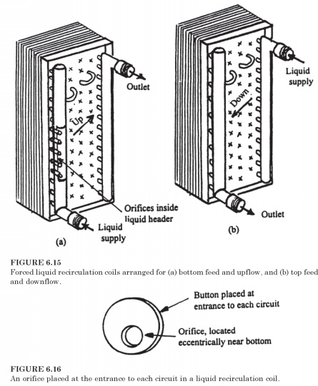
Circuit coils. In direct expansion reels Halocarbon refrigerants, the General direction of refrigerant flow through the chains down in a while to flooded coil to function properly, the General direction of refrigerant flow should be directed upwards. Forced liquid recirculation of the coil can be shorted or as a bottom-up flow (bottom feed), or flow from the top down (top feed), as shown in Fig. 6.15. Coil designer chooses the length of the chain, such that when the refrigerant flows at an appropriate speed gets enough heat passing through the circuit to vaporize the desired fraction of the refrigerant.
Holes in liquid recirculation coils. One refrigerant circuit in rolls Fig. 6.15 consists of six passages and back through the coil. There are a number of parallel passes, and the upper chains in the coil likely to receive inadequate fluid flow. To strive for uniform distribution of the flow of refrigerant, the holes are located at the entrance of each circuit, as shown in the context of Fig. 6.15a. These holes, as shown in Fig. 6.16, thin metal discs with a hole. Holes are, as a rule, eccentrically below, so that the oil that accumulates in the Bay during cooling operation can more easily follow from the coil during the gas defrosting. Often bore diameter greater for the upper circuits to achieve a uniform distribution of refrigerant.
Drain pan for low temperature of the coil. All coils are equipped with a drain pan, because the normal operation of the cooling coil, which works with above-zero temperature, some of the water vapor condenses out of the air. This condensate is going to drain plan and allocate some convenient destination. Coils that are below zero temperatures must be defrosted regularly, and again the drain pan is necessary to collect melted frost to drain it away. Drain pan should be warm, so melted the frost is not refreeze, and when thawing method is by hot gas (see C. 6.22) heat source, available for pallet. Fig. 6.17 shows that the hot gas, which reaches coil for the purposes of thawing first passed through pipes embedded in the drain pan. Hot gas first comes the drain pan, then flows through the coil to defrost.
 .. ..
|

 ..
..